Configure Egress Gateway
TOC
OverviewEgress Gateway vs. Centralized GatewayHow Egress Gateway WorksBefore You BeginConfiguration WorkflowStep 1: Prepare the External Network AttachmentStep 2: Create a VPC Egress GatewayStep 3: Validate the Gateway1. Check the resource status2. Inspect networking inside the gateway Pod3. Confirm traffic forwarding4. Confirm OVN routing policiesOptional: Enable Multi-Replica Load BalancingOptional: Enable BFD-based High Availability1. Enable a BFD Port on the VPC2. Enable BFD on the VPC Egress Gateway3. Verify BFD statusOperations That May Interrupt TrafficAdditional ResourcesOverview
Egress Gateway, also called VPC Egress Gateway, provides stable outbound addresses for Pods in an overlay network. It routes selected workloads through dedicated gateway Pods before the traffic leaves the cluster.
Use Egress Gateway when you need:
- Stable source IP addresses for specific workloads
- Workload-level egress control instead of subnet-level control
- Higher throughput through horizontal scaling
- Faster failover for outbound traffic
Main capabilities:
- Active-Active high availability through ECMP, with horizontal throughput scaling
- Fast failover through BFD, typically in less than 1 second
- Support for IPv4, IPv6, and dual-stack environments
- Fine-grained traffic matching through NamespaceSelector and PodSelector
- Flexible scheduling through node selectors and tolerations
Current limitations:
- Multi-replica deployments require multiple egress IPs
- Source NAT mapping records are not retained
Egress Gateway vs. Centralized Gateway
Compare Egress Gateway with Centralized Gateway to choose the gateway model that best fits your scenario. For centralized mode details, refer to Configure Centralized Gateway.
Selection guidance:
- Choose Egress Gateway when you need workload-level policy control, scalable throughput, and fast failover.
- Choose Centralized Gateway when subnet-level fixed egress and simple operations are sufficient.
How Egress Gateway Works
An Egress Gateway runs as one or more Pods. Each Pod uses two network interfaces:
- One interface connects to the overlay network inside the cluster.
- The other interface connects to the external underlay network.
Traffic from selected Pods is first forwarded to the gateway Pods and then sent to the external network through the underlay interface.
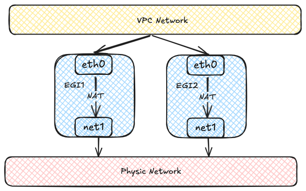
Each Egress Gateway instance registers its address in the OVN routing table. When a Pod in the overlay network accesses the external network, OVN uses source-address hashing to distribute traffic across multiple gateway instances. This provides load balancing and lets throughput scale horizontally as more instances are added.
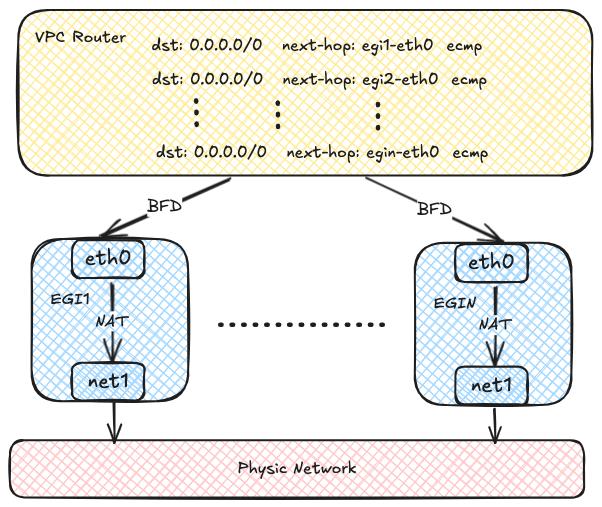
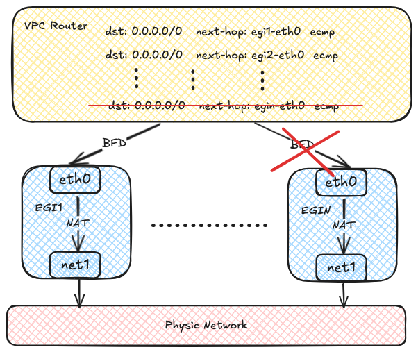
OVN can use BFD to probe multiple gateway instances. If one instance fails, OVN marks the corresponding route as unavailable and quickly redirects traffic to a healthy instance.
Before You Begin
Before you start, make sure the following prerequisites are met:
- Multus CNI Plugin MUST already be installed on the cluster.
- The external underlay network, VLAN, and bridge network are already planned and available.
- You have identified which workloads should use the gateway and whether they require SNAT.
To install Multus CNI Plugin, refer to Deploying the Multus CNI Plugin.
Configuration Workflow
Configure Egress Gateway in the following order:
- Prepare the external network attachment, including the subnet and Network Attachment Definition.
- Create a VPC Egress Gateway resource and specify the external subnet and policies.
- Verify resource status, routes, and traffic forwarding.
- Optionally scale out replicas and enable BFD-based fast failover.
Step 1: Prepare the External Network Attachment
Egress Gateway uses multiple interfaces to connect to both the internal and external networks. Before creating the gateway, prepare the following resources:
- An external subnet
- A Network Attachment Definition (NAD) for that subnet
The following example uses a Kube-OVN underlay subnet as the external network.
This example assumes that the bridge network and VLAN resource external-vlan have already been created for the underlay network.
- Use the Kube-OVN CNI plugin for the secondary network.
- Kube-OVN daemon socket used by the CNI plugin.
- Provider name in the format
<network attachment definition name>.<namespace>.ovn. - The provider used by the subnet. This value MUST match the provider in the NetworkAttachmentDefinition.
- CIDR of the external underlay network.
- Gateway of the external underlay network.
- VLAN resource used by the underlay subnet.
- IP range excluded from automatic allocation. For details, refer to Example Subnet custom resource (CR) with Kube-OVN Underlay Network.
Before using an underlay subnet, make sure the physical network, VLAN, and bridge network are prepared correctly. For environment planning details, refer to Preparing Kube-OVN Underlay Physical Network.
Step 2: Create a VPC Egress Gateway
Create a VPC Egress Gateway resource and define which workloads should use it.
- Namespace where the VPC Egress Gateway instances are created.
- Number of VPC Egress Gateway instances.
- Internal subnet that connects to the internal network. The subnet MUST be an overlay subnet in the same VPC and have enough free IPs for the gateway instances. If not specified, the gateway Pods will use the default internal subnet of the VPC.
- External subnet that connects to the external network.
- External IPs used by the gateway Pods on the underlay network. Each gateway instance is allocated one IP from this list.
These IPs MUST be within the CIDR of the external subnet and should be included in the
excludeIpsrange of the subnet. It's recommended to reserve .spec.replicas + 1 IPs so that a gateway Pod can still obtain an IP in edge cases. - Resource requests and limits for each VPC Egress Gateway instance. If not specified, the default resource requests and limits defined in the VPC Egress Gateway controller will be applied.
- Node selectors used for scheduling the VPC Egress Gateway instances.
- Tolerations used for scheduling the VPC Egress Gateway instances.
- Namespace selectors and Pod selectors used to select Pods that access the external network via the VPC Egress Gateway.
- Policies for the VPC Egress Gateway, including SNAT and subnets/ipBlocks to be applied.
- Whether to enable SNAT for the policy.
- Subnets to which the policy applies.
- IP blocks to which the policy applies.
This example creates a VPC Egress Gateway named gateway1 in the default namespace.
Traffic that matches the selectors and policies is forwarded through the external subnet underlay-ext.
In this example, that includes:
- Pods in the ns1 namespace
- Pods in the ns2 namespace with the label
app: myapp - Traffic related to the subnet1 subnet
- Traffic related to the CIDR 10.18.0.0/16
Pods matching .spec.selectors are always SNATed by the gateway.
Step 3: Validate the Gateway
After creating the gateway, confirm that it is ready and forwarding traffic as expected.
1. Check the resource status
Start with the basic resource status:
Then check the detailed gateway information:
Finally, verify that the gateway workloads are running:
2. Inspect networking inside the gateway Pod
Inspect IP addresses, routing entries, and iptables rules inside the gateway Pod:
3. Confirm traffic forwarding
Capture packets in the gateway Pod to confirm that traffic is forwarded through the gateway:
4. Confirm OVN routing policies
OVN Logical Router policies are created automatically for the selected traffic:
- Logical Router Policy used by the VPC Egress Gateway to forward traffic matched by .spec.policies.
- Logical Router Policy used by the VPC Egress Gateway to forward traffic matched by .spec.selectors.
Optional: Enable Multi-Replica Load Balancing
Before scaling out replicas, make sure to prepare enough external IPs in the external subnet and specify them in .spec.externalIPs.
To enable ECMP load balancing and scale throughput horizontally, increase .spec.replicas:
Optional: Enable BFD-based High Availability
BFD-based failover depends on the VPC BFD LRP. Enable it in the following order.
1. Enable a BFD Port on the VPC
First, enable a BFD Port on the VPC:
- Whether to enable the BFD Port.
- IP address of the BFD Port, which MUST be a valid IP address that does not conflict with ANY other IPs/Subnets.
- Node selector used to select the nodes where the BFD Port runs in Active-Backup mode.
The Vpc resource ovn-cluster exists by default. You can edit it directly to enable the BFD Port.
After the BFD Port is enabled, a dedicated BFD LRP is automatically created on the OVN Logical Router:
- BFD Port created on the OVN Logical Router.
2. Enable BFD on the VPC Egress Gateway
Then enable BFD on the VPC Egress Gateway by setting .spec.bfd.enabled to true:
- VPC to which the Egress Gateway belongs.
- Internal subnet to which the Egress Gateway instances are connected.
- External subnet to which the Egress Gateway instances are connected.
- External IPs assigned to the Egress Gateway instances.
- Whether to enable BFD for the Egress Gateway.
- Minimum receive interval for BFD, in milliseconds.
- Minimum transmit interval for BFD, in milliseconds.
- Multiplier for BFD, which determines the number of missed packets before declaring a failure.
This example creates a VPC Egress Gateway named gateway2 with two replicas and BFD enabled. If one instance fails, the BFD session goes down, OVN marks the route as unavailable, and redirects traffic to the healthy instance.
Failover detection time depends on the BFD settings. Use the following formula: break time = (multiplier + 1) * max(minRX, minTX). With this sample configuration, failover detection is approximately 500-600 ms.
Existing connections may be interrupted during failover and require reconnection. New connections can still be established normally.
3. Verify BFD status
Check the VPC Egress Gateway status:
Then check the BFD sessions:
If all gateway instances are down, egress traffic handled by the VPC Egress Gateway is dropped.
Operations That May Interrupt Traffic
The following operations may briefly interrupt egress traffic because they delete or recreate gateway instances:
- Changing the number of replicas
- Changing configuration such as internal or external IPs, node selectors, or BFD settings
- Upgrading or downgrading Kube-OVN if .spec.image is not specified
- Manually deleting an Egress Gateway Pod